Report from the weekend.
I snuck into the workshop late Saturday evening and did some more checking and tinkering.
I decided to try RTV-ing the rocker cover:

I also realised that the fuel line was very very close to the spark-plug cap, and then remembered that I'd seen a 90 degree fuel union somewhere... so dug it out and this is a lot neater (if needing a bit of a clean up)

I'd decided to forego the Ardningly bike-jumble in favour of actually getting the JAPton out and visiting the local classic meet.
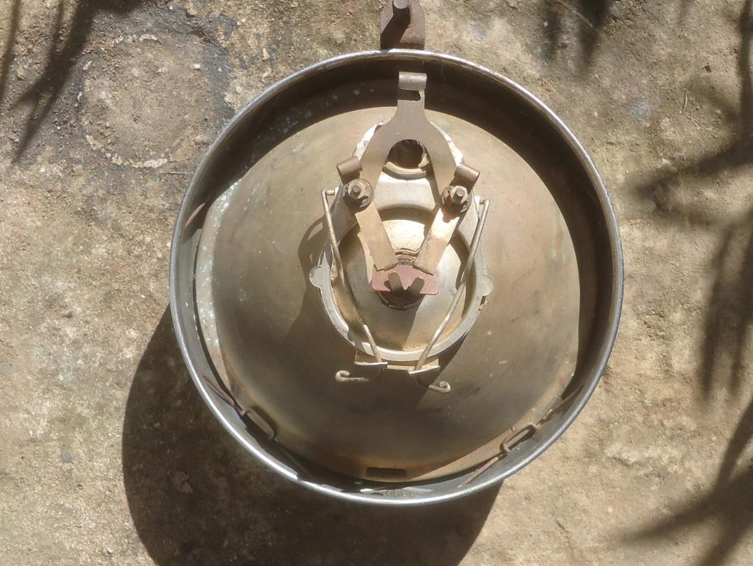
So, Sunday morning I checked the oil:

4.6cm as a baseline.

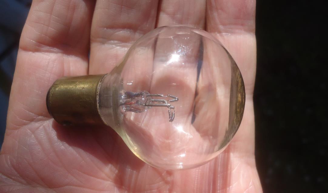
Oh - and I added the finishing touch..


Made it to the meet alright (even though I went to the wrong location first..... D'oh!)

Got a fair bit of interest from everyone, mainly because it's 10x louder than everything else, so your arrival is noted....

On the way home I nearly had a KSI, I was coming up for the turning into my driveway, a right hand turn, so I stuck my arm out for at least 5 seconds (I learnt how to make VERY OBVIOUS hand signals a long time ago riding Dad's old bike collection), brought my hand back to make the turn, and the ABSOLUTE $%^ in the Merc CLK tailgating me OVERTOOK ME.
IF he'd been a microsecond less impatient, he would have had me over his bonnet.
I was so enraged I chased him down with the horn blaring and gave him a piece of my mind (the only bit working, sadly). Didn't really resolve anything, but I think I did get an apology out of him... (eventually, after I had to apologise for using bad words at him, wtf?? He was at least 30, has he not lived in the real world? :wtf: ).
Post-mortem of the ride: The RTV on the rocker cover seems to have worked, but oil is still pouring out of the engine somewhere. The most obvious location would be the base of the push rods, and it's got me thinking: I reckon it needs a crankcase breather.
The engine, as designed, has a crankcase that is (essentially) open to atmosphere, so the down-stroke pressure wave has somewhere to go. Now that my engine has the return pump blocking that exit route, and there is no longer a cable-operated decompression lever, there's no crank-case breather. The De-comp system in the timing chest was cable-operated, so there WAS a route to atmosphere through that cable (not great, but there).
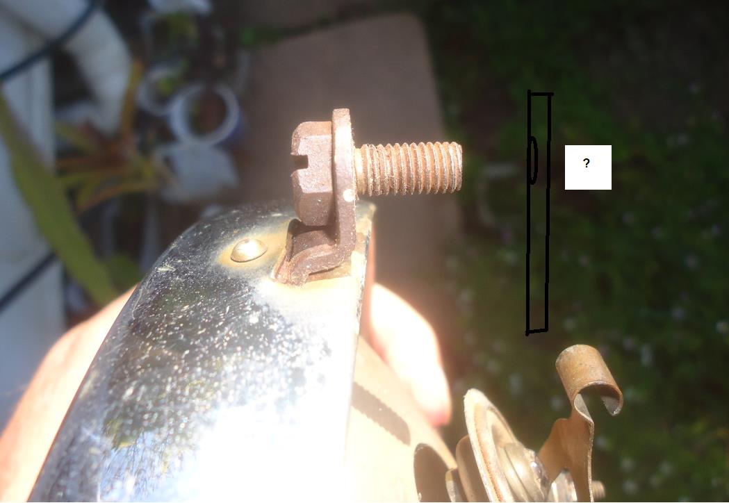
I'm going to talk to one or two people about it, but I'm pretty sure I need to put a breather tube into the crankcase/timing chest, luckily, there's a very obvious and handly location for one.
I also reduced the amount of oil flowing to the head, siply to reduce losses but if the fitment of the breather works well, I'll wind it up again to make sure the head gets enough (it doesn't want too much otherwise the oil overwhlems the valve-stem requirements and gets into the head). I reduced it down to about 1 drop every 7 -10 seconds (it's difficult to get an accurate measure with the random tickover...)


 Recent Posts