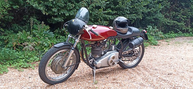
I tinkered with the JAPton last night. (Life is busy at the moment, so I don't often get into the workshop).
It's all back together but wasn't running properly - lots of spitting back and backfiring in the exhaust.
Got it running, and spent about an hour going back and forth between the ancient Monobloc "Notes" leaflet (Dad had some photocopies so at least I wasn't getting the original filthy!)* Eventually got my head around it and realised that the damn thing was running "weak" in the mid-range and so pulled the needle up a notch (the first thing I'd done was lower it a notch to the "top" notch, it refused to run on that setting). Now it's in the middle of the needle's range its actually running pretty well (once it's hot). The occasional spit back or backfire, but I think I can live with that for now.
Happy bunny!
During the course of the session I'd spotted a couple of nuts that had fallen on the floor - one was an engine bolt that (in hindsight) I know was loose - the primary chase mounting lug is held in place by it and I'd simply forgotten it was loose.
The other was the nut off the forward connection for the gear linkage.... it's a nyloc, but I discovered that Dad had cut the bolt for it down so short that the threads aren't actually engaging the nylon locking collar! ( ffs). Couldn't be arsed at that point to root around for a better bolt so I just pushed the nut on upside down. Hardly ideal but it'll do to hold it all together while I figure out another issue.
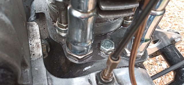
I was wiping some oil off the top of the crankcase when I discovered something that terrifies me...

That bolt, the one between the push-rod tubes, is loose, and it
won't go tight.

It just revolves.
Now - I may be wrong.... but, to me, that indicates that there's a friggin NUT on the other side of the case, that is loose, and is hanging on the threads of the bolt.
I
may be wrong, and the loose bolt is caused by the threads on either the bolt or the casing being thoroughly knackered.
But - either way, the mininum work needed before I can do
anything with the bike is to strip the entire right side of the engine away to check what's going on in the timing box. :roll:
I can't take a chance on the probability of a nut dropping into the timing box.
So - The JAPton is unlikely to see tarmac again this side of Easter, simply because I know that I've never done any of this stuff before and I'll be taking things very slow and thoroughly checking it all, and researching how it all works. Oddly, for all the tinkering I've done over the years, this is the first time I've ever had to actually do the timing on anything.
I also seem to have been thrown off / barred from the JAP Engine Facebook group I was on - so also need to find a J.A.P. specialist source of further information.
Dagnabbit.
* I must get a copy of that leaflet blown up and laminated. I did the same with the exploded diagram for the carb and it's an invaluable reference sheet).